On this page
- Where generator exhaust noise comes from
- What generator silencer grades mean
- From a noise limit to a required insertion loss
- Back pressure: the budget the silencer has to share
- Installation details that decide the result
- Generator exhaust silencers in service
- What to have ready when you specify a generator exhaust silencer
A generator exhaust silencer is chosen on three numbers: the noise level the exhaust must reach at a stated position, the insertion loss the silencer must deliver in the octave bands where the engine is loud, and the pressure drop it may add without pushing the engine past its maximum exhaust back pressure. Catalogue grades such as industrial, residential, critical and hospital are shorthand for the first number only. This article explains what the grades mean, how to turn a noise limit into a required insertion loss, how the back-pressure budget constrains the design, and what data to have ready when you specify a silencer for a diesel or gas genset.
Where generator exhaust noise comes from
A reciprocating engine discharges its exhaust in pulses, one per cylinder firing. In a four-stroke engine each cylinder fires once every two revolutions, so the pulses reaching an exhaust pipe repeat at the firing frequency:
f = n × z / 120
where f is the firing frequency in Hz, n the engine speed in rpm and z the number of cylinders discharging into that pipe. On a V-engine whose banks have separate exhaust outlets, count the cylinders feeding each outlet.
| Cylinders per pipe | 1,500 rpm (50 Hz) | 1,800 rpm (60 Hz) |
|---|---|---|
| 6 | 75 Hz | 90 Hz |
| 8 | 100 Hz | 120 Hz |
| 12 | 150 Hz | 180 Hz |
| 16 | 200 Hz | 240 Hz |
| 20 | 250 Hz | 300 Hz |
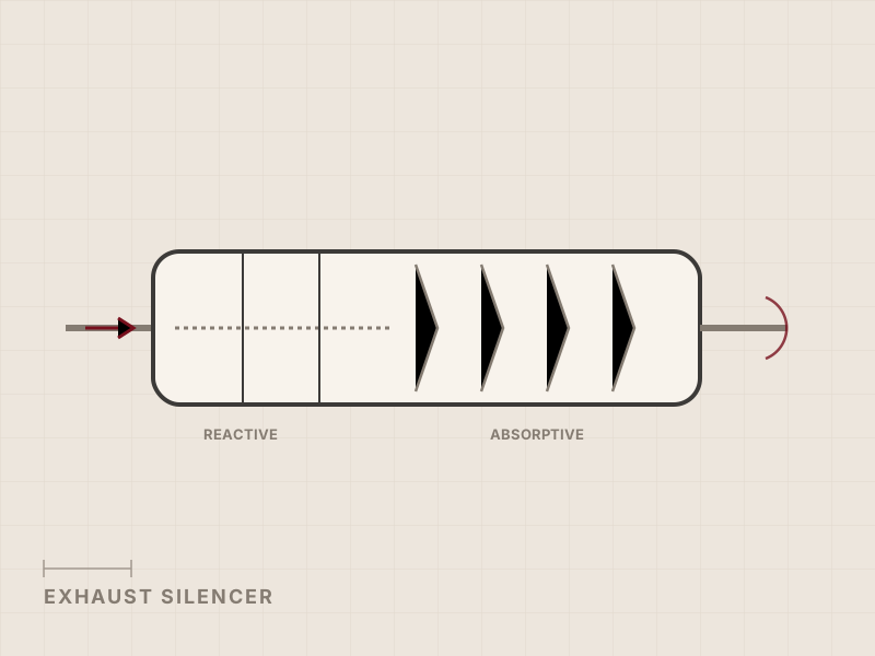
A genset that feeds the grid runs at a fixed speed, so its firing tone and the first harmonics sit at fixed frequencies, mostly in the 63 to 250 Hz octave bands; for the same number of cylinders, medium-speed engines at 750 or 1,000 rpm put the tone lower still. That is where the silencer does its hardest work. Low-frequency sound diffracts around buildings and barriers and loses little to air absorption, so it is the part of the exhaust noise that reaches the neighbours. Broadband noise from the turbocharger and the gas flow fills the mid and high bands on top. Most generator exhaust silencers therefore combine reactive chambers for the firing tones with an absorptive section for the broadband remainder; our guide to exhaust silencer types explains both mechanisms.
What generator silencer grades mean
Generator silencer catalogues, particularly North American ones, sort their products into grades by nominal attenuation. The grade names are common across manufacturers; the numbers behind them are not. These are the approximate ranges typically quoted:
| Catalogue grade | Attenuation typically quoted |
|---|---|
| Industrial | 12 to 20 dB(A) |
| Residential | 18 to 25 dB(A) |
| Critical | 25 to 35 dB(A) |
| Hospital, super critical | 32 to 42 dB(A) |
| “Extreme” and similar | 40 dB(A) and above |
These ranges are manufacturer conventions, not definitions: each catalogue sets its own band, and the same grade name can differ by several dB from one supplier to the next. The Electrical Generating Systems Association (EGSA) published a rating guide in 2014 to make ratings comparable. EGSA 201S-2014 rates generator exhaust silencers in eight classes by dynamic insertion loss, in 5 dB steps from Class 1 (10 to 15 dB) to Class 8 (45 to 50 dB) [1]. Dynamic insertion loss is the change in sound level at a point when the silencer is inserted into the exhaust system with the engine running.
A grade or class is a useful shorthand when you buy a catalogue silencer for a small genset. On a project with a permit limit, it leaves three questions open:
- Which spectrum it was rated on. A dB(A) attenuation figure is the difference between two A-weighted totals, so it depends on the spectrum it was measured with. The same silencer treats a 200 Hz firing tone and a 2 kHz turbocharger whine very differently, so its dB(A) reduction on one engine is not its reduction on another.
- Where the result applies. A grade describes attenuation. A permit sets a level at a location, and only the level at that location shows whether the site complies.
- What it costs in back pressure. Two silencers of the same grade can differ widely in pressure drop, depending on body size and internal design.
That is why Axces engineers each exhaust silencer to order, against the engine’s spectrum, the project’s noise limit and the engine’s back-pressure limit, rather than selling grades.
From a noise limit to a required insertion loss
The required insertion loss is the gap, band by band, between what the bare exhaust would produce at the assessment point and what the limit allows there. The airborne noise of a complete generating set is measured to ISO 8528-10 [2]; for the silencer design you need the exhaust contribution on its own. In practice:
- Start from the unsilenced exhaust noise. Engine and genset data sheets usually state it, often as a sound pressure level at 1 m from the open outlet. Ask for the octave-band spectrum, not only the dB(A) total.
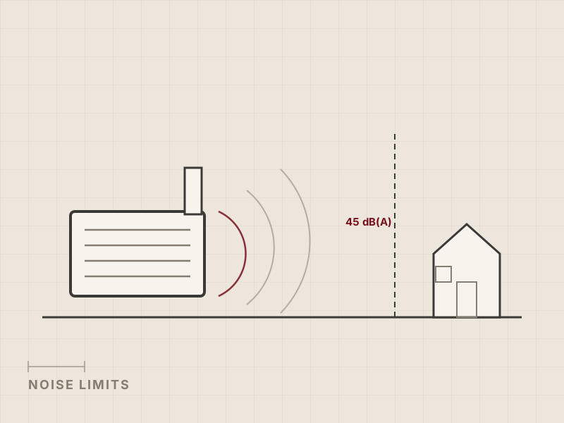
- Fix the target and where it applies. A level at 1 m from the outlet is common in project specifications; an environmental permit usually sets a level at the site boundary or at the nearest dwelling, often lower at night.
- Carry the source to that position. Account for distance, the direction the outlet points, screening by buildings, and the number of gensets that can run at the same time: ten identical exhausts running together are 10 dB louder than one.
- Subtract band by band, and leave room for the other sources. The engine casing, radiator fans and enclosure ventilation also contribute at the receiver, so the exhaust only gets a share of the limit.
- Check the silencer’s own flow noise. Gas moving through the silencer generates noise that rises steeply with velocity and sets a floor under the outlet level. A small silencer with high internal velocities, chosen to save space, can make a low target unreachable.
Insertion loss is not the same as the net reduction at the receiver, and the two get confused in specifications; our guide to specifying dB(A) noise reduction targets covers the difference. Laboratory insertion loss, flow noise and pressure loss of a silencer are measured to ISO 7235 [3], and measurements on an installed silencer to ISO 11820 [4]. For the permit side of a standby fleet, see our article on noise limits for data center backup generators.
Back pressure: the budget the silencer has to share
Engine manufacturers state a maximum allowable exhaust back pressure on the engine data sheet, at the engine’s exhaust outlet and at rated load. Above that limit the engine loses power, burns more fuel and runs at higher exhaust temperatures, and the installation falls outside the conditions the engine is rated for.
The limit applies to the whole exhaust system, not to the silencer alone. Everything between the engine outlet and the atmosphere spends part of it:
| Part of the exhaust line | What sets its share of the back pressure |
|---|---|
| Flexible connection and pipework | Pipe diameter, length and gas velocity |
| Bends, branches and transitions | Number and radius of bends; how the flows of merged engines join |
| Aftertreatment (SCR, DPF), where fitted | Catalyst and filter design; a particulate filter’s drop rises as it loads with soot |
| Silencer | Internal design, body size and the attenuation required |
| Stack outlet and rain protection | Rain cap or flap design and outlet velocity |
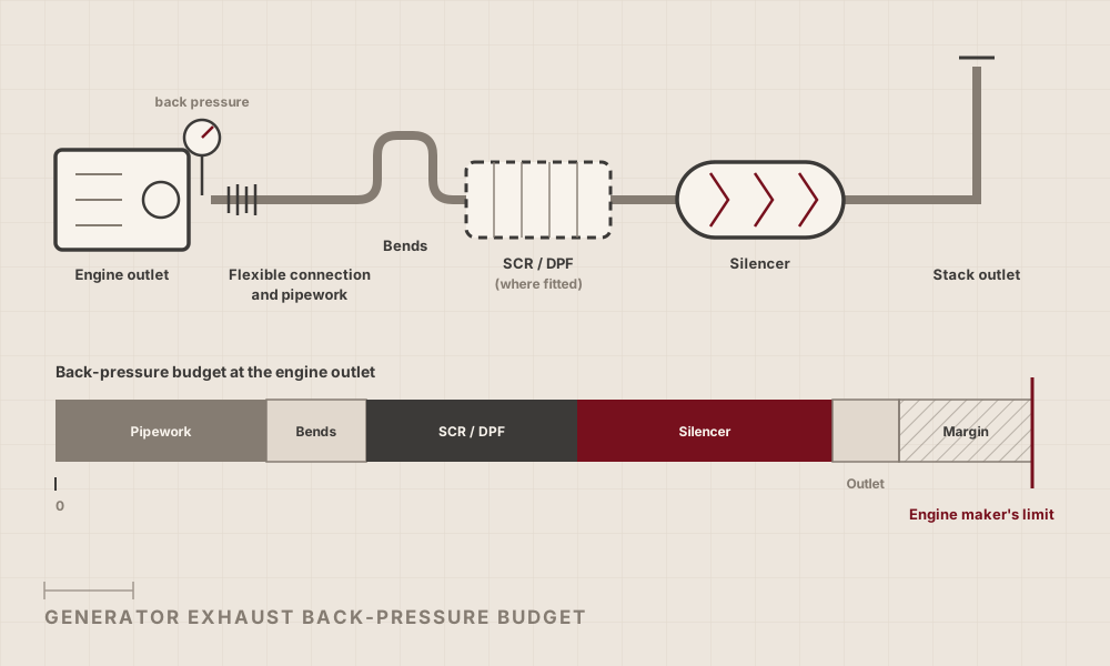
The physics that decide each share are simple. The pressure drop of a component rises with the square of the gas velocity. At a given mass flow, velocity rises as the gas gets hotter and as the cross-section shrinks. At 500 °C, exhaust gas has well under half the density of air at ambient temperature, so it needs far more flow area per kilogram. For a fitting with a fixed loss coefficient, the pressure drop at the same mass flow scales with the inverse fourth power of its diameter: a bore 10 % smaller raises the loss by about 50 %. Pipe size is therefore usually the cheapest place to recover back pressure.
Attenuation and pressure drop pull against each other. At the same body size, more attenuation usually means more chambers, more flow reversals or tighter perforated tubes, and every one of them adds pressure drop. A higher grade without a back-pressure penalty is possible, but it costs volume: larger chambers and a longer absorptive section at lower velocity. In practice the real price of a stricter noise limit is the size and weight of the silencer, and the space and support it needs.
Three situations need the budget worked out with particular care:
- Aftertreatment in the same line. An SCR reactor and a particulate filter spend part of the same budget, and a filter’s share should be taken in its loaded state, before regeneration. An SCR housing can also be designed to provide part of the attenuation, which frees budget for the rest of the line; our article on retrofitting emission control to generators covers that case.
- Merged exhausts. When two engines discharge into one stack, the ducting has to be designed so that neither engine pushes back pressure onto the other, whether one or both are running.
- Retrofits. A quieter silencer on an existing genset inherits the old pipework. Measure the back pressure at full load before sizing it, not after.
Whatever the design, measure the back pressure at the engine outlet at full load during commissioning, and record it with the noise measurement.
Installation details that decide the result
A well-sized silencer still underperforms if the installation around it leaks noise or loads the engine. The details that matter most:
- A flexible connection at the engine outlet, so the turbocharger carries neither the weight nor the thermal growth of the exhaust line. Engine manufacturers limit the load allowed on the outlet flange.
- Independent support for the silencer and pipework, with guides and expansion provisions for the growth from cold to full exhaust temperature.
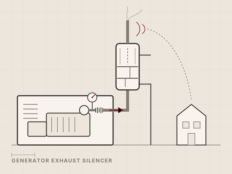
- Breakout noise control. The pipe between engine and silencer radiates noise through its wall. Inside an enclosure or plant room, keep that run short and insulate it, or the enclosure ventilation carries out the noise the silencer was meant to stop.
- A drain at the lowest point, and rain protection at the outlet that does not eat into the back-pressure budget.
- Outlet height and direction. A vertical outlet above the roofline directs the remaining noise upwards, away from receivers at ground level, and helps the exhaust gas disperse.
Axces designs the silencer together with its supports, connections and, where needed, the chimney, using carbon, stainless and high-alloy steels rated to 550 °C continuous, and builds it at our own facility, Axces Production in Poland.
Generator exhaust silencers in service
Two Axces projects show how exhaust silencers are specified for engine fleets: as a level at 1 m from the outlet, not as a grade.
| Project | Engines and scope | Noise requirement met |
|---|---|---|
| Hyperscale data center in Germany | Diesel backup gensets; 14 exhaust systems, each an integrated silencer and self-supporting chimney | 75 dB(A) at 1 m |
| 450 MW gas-engine power plant in the UK | 95 gas engines of 4.5 MW in 48 exhaust systems, 47 of them carrying two engines into one stack | 69 dB(A) at 1 m, with one or both engines running |
In both projects the silencer was designed as one system with the chimney that carries it; the chimneys are designed to EN 13084-7 and the complete systems are CE marked.
What to have ready when you specify a generator exhaust silencer
- Engine make, model and rating; speed; number of cylinders and exhaust outlets
- Exhaust data at rated load: mass or volume flow and temperature, and part-load data if the genset runs there for long periods
- The engine’s maximum allowable exhaust back pressure, and the share already taken by pipework and any SCR or DPF
- Unsilenced exhaust noise from the engine data sheet, ideally as an octave-band spectrum
- The noise requirement: level, position (1 m from the outlet, site boundary or nearest dwelling), basis (permit or project specification), and whether it applies at night
- How many gensets can run at the same time, and whether exhausts are merged
- Exhaust layout: pipe sizes and route, outlet height and orientation, available space and support structure
- Fuel and aftertreatment: diesel, gas or HVO; SCR or DPF in the same line
- Design code, material requirements and site conditions (wind, seismic, minimum ambient temperature)
With this data a silencer can be sized against your limit and your back-pressure budget at the same time, instead of against a grade.
If a genset on your project has a noise limit to meet, see our exhaust silencers for gensets and engines, or request a quote for a generator exhaust silencer with the data above and our engineers will come back with a sizing proposal.
References
- Electrical Generating Systems Association. EGSA 201S-2014, Guide for Rating Generator Exhaust Silencers: rating classes by dynamic insertion loss for exhaust silencers on reciprocating engines used for power generation. https://egsa.org/Portals/0/Documents/Standards/STD201S.pdf
- International Organization for Standardization. ISO 8528-10:2022, Reciprocating internal combustion engine driven alternating current generating sets, Part 10: Measurement of airborne noise. https://www.iso.org/standard/74983.html
- International Organization for Standardization. ISO 7235:2003, Acoustics: Laboratory measurement procedures for ducted silencers and air-terminal units: Insertion loss, flow noise and total pressure loss. https://www.iso.org/standard/30385.html
- International Organization for Standardization. ISO 11820:1996, Acoustics: Measurements on silencers in situ. https://www.iso.org/standard/20231.html