Pressure Control · Noise Control
Four two-stage diffusers for a petrochemical plant in Central Asia
Four two-stage diffusers in three sizes for the control valves on the propylene lines of a petrochemical plant in Central Asia. In each line the valve takes a small part of the pressure drop and the diffuser's two perforated stages take the rest, on flow cases of up to 825,000 kg/h. Designed to ASME VIII Division 1 for -38 to +100 °C.
- Industry
- Oil & Gas
- Location
- Central Asia
- Year
- Solutions
- Pressure ControlNoise Control
- 4Two-stage diffusers
- 825 t/hLargest flow case
- −38 °CMin. design temp.
- ASME VIIIDivision 1
The challenge
A petrochemical plant in Central Asia needed diffusers behind four control
valves on its propylene lines. The order came through the manufacturer of the
valves. Three duties were involved: two take propylene from 12.28 bar(a) at
the valve down to 1.65 and 5.41 bar(a), the third from 22.86 bar(a) down
to 8.4 bar(a). The 5.41 bar(a) duty has two valves, each with its own
diffuser, and the governing flow cases run up to 825,000 kg/h.
Taking drops that size in one step across the valve trim gives high velocity
and noise at the valve outlet. Each diffuser had to share the drop with its
valve, connect a 10- or 20-inch inlet to a much larger outlet line, and meet the
project’s minimum design temperature of -38 °C.
Our approach & engineering
Axces designed four double-stage diffusers of its 2LDF type, in three sizes,
from the process data for each valve: two flow cases per valve, the pressure at
the valve and at the diffuser inlet, the operating temperature and the pressure
downstream.
Splitting the pressure drop
In every line the valve takes only a small part of the drop and the diffuser’s
two perforated stages take the rest. On the line that ends at 1.65 bar(a),
the diffuser takes the propylene from up to 11.43 bar(a), a pressure ratio of
almost 7. Each diffuser also widens from its inlet to a larger outlet (10 to 18 inch,
10 to 30 inch and 20 to 36 inch), so the expanded gas leaves at a lower
velocity. Our article on
diffuser design for pressure letdown
explains the principle.
In the higher of the two flow cases for each duty:
10" × 18", class 300:400,000 kg/hat77 °C, from20.5to8.4 bar(a)across the diffuser10" × 30", class 150:230,000 kg/hat41 °C, from11.43to1.65 bar(a)- 2 ×
20" × 36", class 150:825,000 kg/hat41 °C, from11.50to5.41 bar(a)
Pressure parts for low temperatures
All four diffusers are designed to ASME VIII Division 1 (2017 edition) for
-38 to +100 °C, the class 300 unit for 34.2 bar(g) and the class 150 units
for 16.7 bar(g), with a 1.5 mm corrosion allowance. Shells and heads are
SA-516 Gr. 60, flanges SA-105N and nozzles SA-106 Gr. B, with weld-neck
flanges to ASME B16.5 and, for the 30- and 36-inch outlets, ASME B16.47
Series A. Impact testing was included as the design code requires, together
with 10% radiographic or ultrasonic examination of the pressure-containing welds
and a hydrostatic test of each diffuser.
- Two perforated stages that take the larger share of each pressure drop
- Outlets two to three sizes larger than the inlets, to bring the velocity down
- Designed to
ASME VIII Division 1for-38to+100 °C, with impact testing - Painted to the project’s painting specification
Scope of supply
- 1 × two-stage diffuser, 10” × 18”, class 300, Ø600 mm × 800 mm
- 1 × two-stage diffuser, 10” × 30”, class 150, Ø762 mm × 800 mm
- 2 × two-stage diffuser, 20” × 36”, class 150, Ø914 mm × 900 mm
- Drawings, strength calculations and data sheets for each diffuser
- 3.1 material certificates, weld procedure qualifications and a manufacturing data book
- Closed wooden cases for transport
Results
The four diffusers were painted, packed in closed wooden cases and shipped in July 2020.
- Four diffusers in three sizes, for flow cases of up to
825,000 kg/hof propylene - Pressure drops down to
1.65 bar(a)taken in two perforated stages - Designed to
ASME VIII Division 1for-38to+100 °C - Each diffuser hydrostatically tested, with impact testing for the low design temperature
Related reading
- Diffuser design for safe pressure letdown and venting: how a diffuser breaks one large jet into many smaller ones
- Combined pressure and noise control: when one device must do both: when a letdown device also has to meet a noise limit
- Sizing a vent silencer for high-pressure gas blowdown: the data a gas vent is sized from
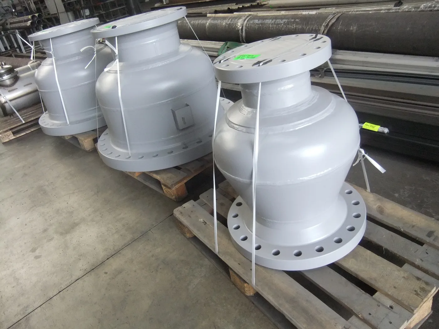
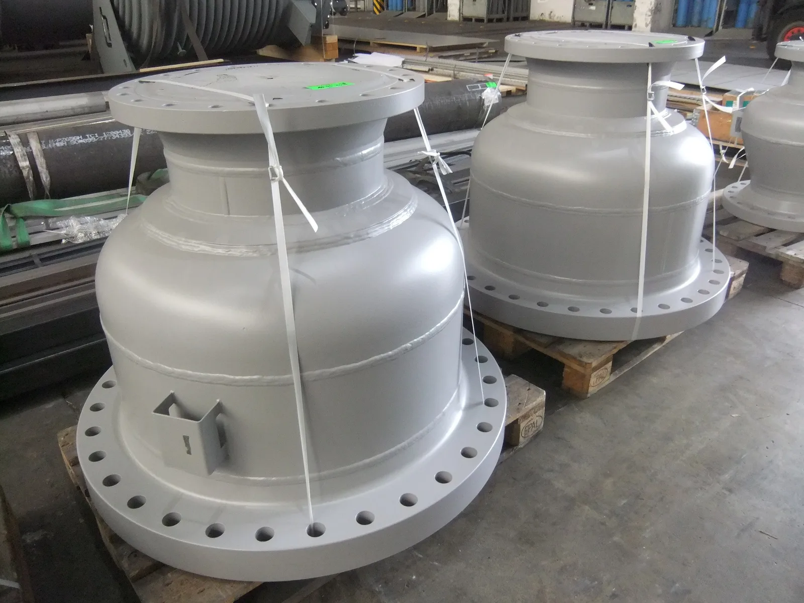
Three of the four diffusers, painted and strapped for shipment. 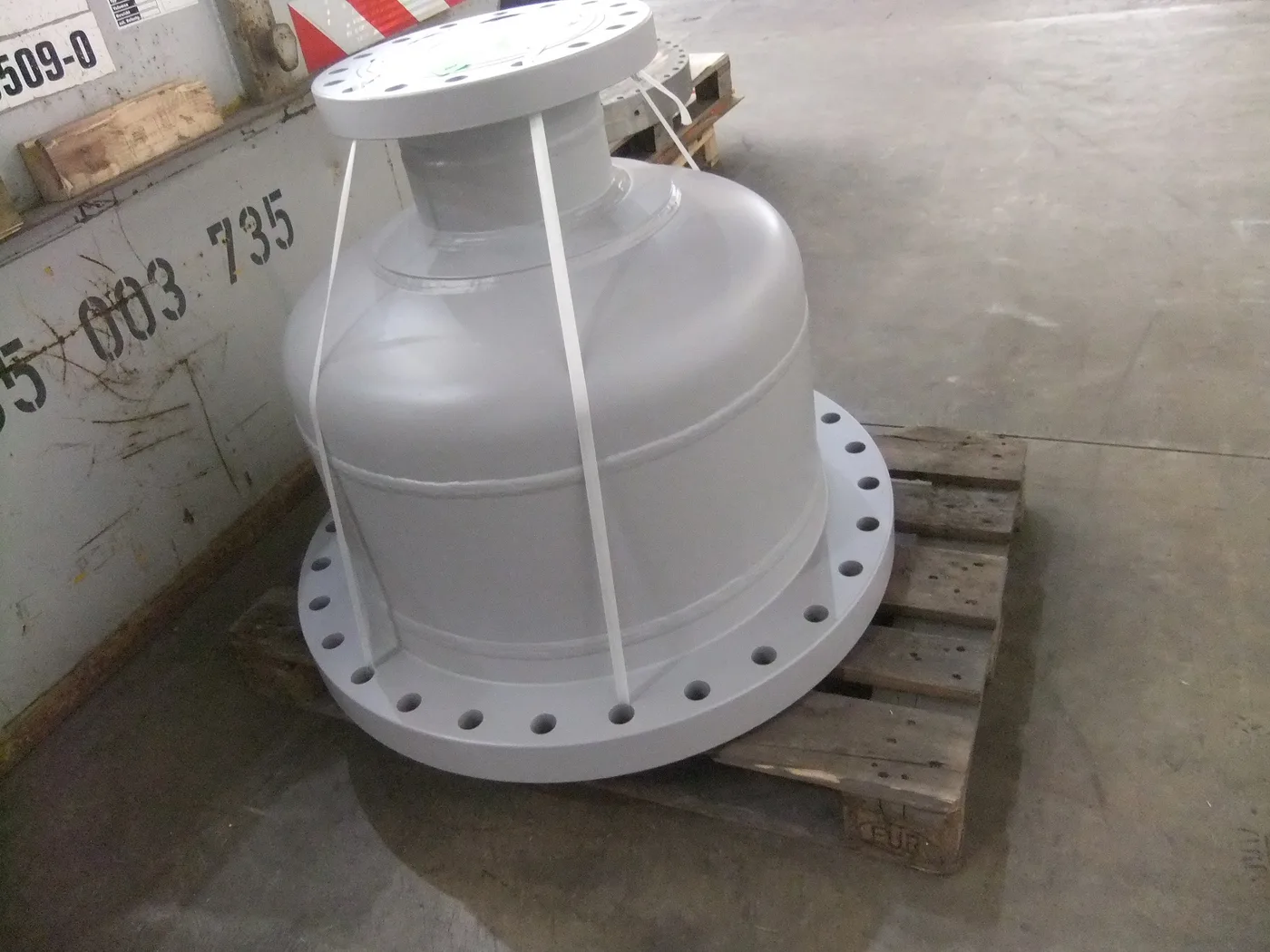
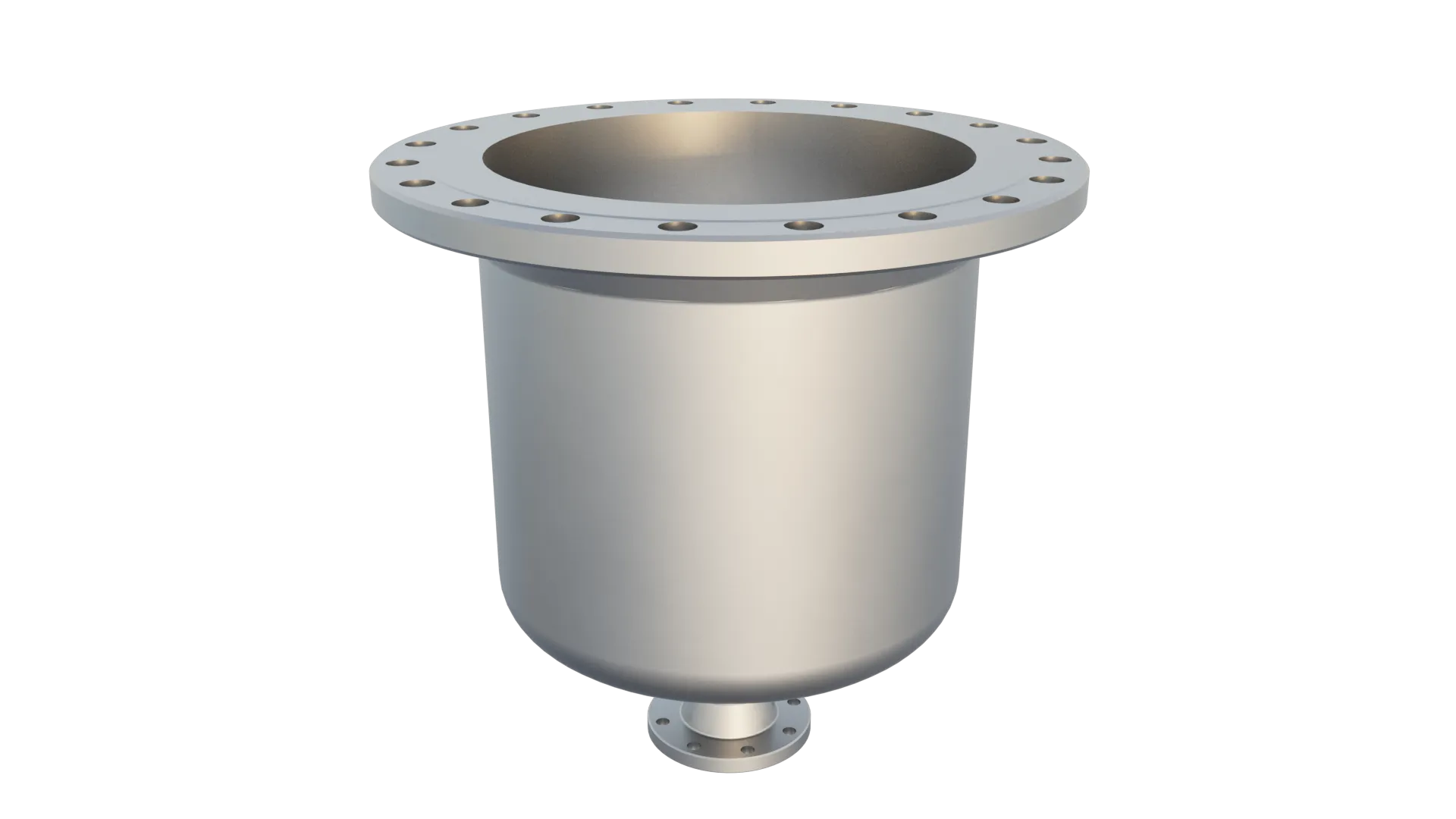
Each diffuser widens from its inlet flange (top) to a much larger outlet flange (bottom).